Fire Doors are designed to close automatically from a fully open position – activation of the door in the down position may cause damage. Fire Doors are not designed for use in high cycle applications – a secondary non rated door is recommended in those situations.
Acceptance of the listing for variations in wall construction should be verified with the building authority having jurisdiction.
Fire Doors come with a 2 year/ 20,000 cycle warranty. See Warranty Page for details.
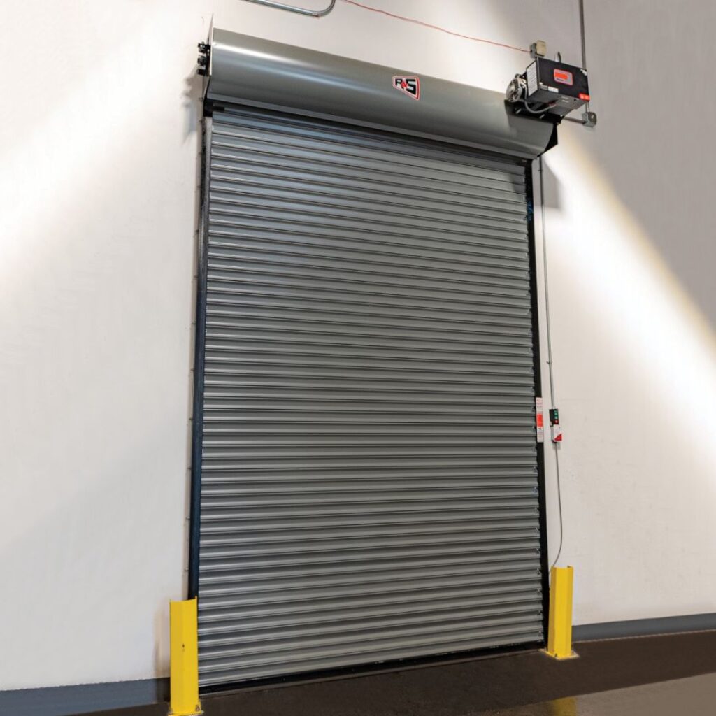
Part 1 General
1.01 Summary
A. Fire doors excluding design, construction and preparation of opening; finish or field painting; access panels; electrical wiring, conduit, wire, fuses and disconnect switches.
1.02 Quality Assurance
A. Certification: Fire doors are labeled or certified by Underwriters Laboratories, Warnock Hersey for the hourly rating, wall construction and size allowed by the listing. Fire doors not in compliance with listing requirements are certified by the manufacturer.
Part 2 Products
2.01 Materials
A. Manufacturing: R & S Manufacturing, model R ___
B. Mounting: Face of wall or between-jamb
C. Operation: Push-up to 8′ wide and high and chain hoist on larger sizes is standard; awning crank, crank box or motor operation are optional.
D. Automatic closing: Thermally activated by 165° fusible links, with the closing speed regulated by a governor device operative only during automatic closing.
E. Curtain: Interlocking type ___ slats are roll formed from galvanized steel coil. Gage of slats is as required by the listing. Endlocks are riveted to slats to maintain curtain alignment. Bottom of curtain is reinforced by a double steel angle footpiece.
F. Guides: Steel structural steel angles form curtain guides and are bolted to structural steel wall angles. Sizes of guides are as required by the listing.
G. Brackets: Steel plate brackets are bolted to wall angles to support curtain and barrel and provide mounting for hood.
H. Barrel: Minimum 6″ diameter steel pipe houses torsion spring assembly and supports curtain with a maximum deflection of .03 inch per foot of width. Torsion springs ar mounted on a continuous cold rolled steel shaft, adjustable by a tension wheel outside one bracket.
I. Hood: Formed from minimum 24 gauge galvanized steel sheet, reinforced with top and bottom flanges to limit deflection. A thermally released integral flame baffle is provided when required by the listing.
J. Locking: Chain lock with chain operation and slide bolt locks with push-up or crank operation.2.02 Finish
A. Slats and hoods are pre-finished with a baked on grey polyester primer before forming. Footpiece, guides and brackets receive one coat of rust inhibiting grey primer.
Part 3 Execution
3.01 Installation
A. Fire doors are to be installed by an R & S authorized representative in accordance with R & S installation instructions and NFPA 80.
3.02 Testing
A. Fire doors are to be drop tested and witnessed for proper operation and full closure after installation.
3.03 Schedules
A. NFPA-80 and model code groups mandate annual inspection and testing of fire doors to check for proper operation and full closure.
Fire Door Options
LiftMaster Release Devices (Click for Details)
Smoke Detectors: Photoelectric (detects smoke and heat) require connection to a release device with compatible voltage.
Perimeter Gasketing: Brush seals factory applied to guides and footpiece, field installed on header, to aid in smoke and draft control.
Vision Lites: Single or multiple 4″ wide cut-outs, glazed with clear wire glass (1 1/2 hour rating).
Powder Coat Finish: Available on all exposed surfaces, powder coating is a durable and decorative finish for steel or aluminum surfaces that provides longer life and requires less maintenance than a standard finish. Available in a variety of colors. Consult factory for color selection, applications and limitations.
Galvanized Finish: Hot dip Galvanizing available on footpiece, guides and brackets
VIBRATECH ® Viscous Speed Governor: Available on R & S Manufacturing, Inc. fire doors for new construction and retro-fit. Viscous speed governor is a patented device allowing for a smooth and quiet descent of fire doors, replaces standard ductile iron governor, and recommended on larger certificate size fire doors, either manual or motorized operation. Viscous speed governor is U.L. listed and conforms to ASTM E152, CAN4-S104, NFPA 252, and UL 10B. Simple, maintenance-free design and construction, with a one year warranty.
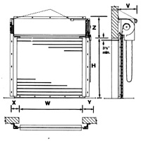
Side Room Requirements
Opening Width ‘W’
X”
Y”
Up to 8′
6-5/8
8
8′-12′
7-1/8
9-1/2
12′-15′
7-1/2
10
15′-18′
9-1/2
10-1/2
18′-24′
10-1/2
11-1/2
Add 1 1/2″ to ‘Y’ for crank or motor.
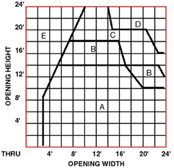
Head Room Requirements
Area
Z”
V”
A
21-3/4
20
B
23-1/4
21-1/2
C
25-1/4
23-1/2
D
29-1/4
27-1/2
E
Consult
Factory
Consult
Factory
Slat Options
Type 30 Large Curved Slat
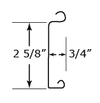
Type 25 Large Flat Slat
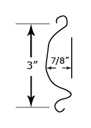
Standard curved slat for use on all service doors where strength and durability are a consideration. Available in 24, 22, 20, or 18 gauge galvanized steel. Also for use on all fire doors.
Standard flat slat for use on all service doors where environmental conditions are a consideration. Available in 24, 22, 20, or 18 gauge galvanized steel. Also for use on all fire doors, especially those requiring gasketing.
Type 20 Small Curved Slat
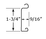
Type 18 Small Flat Slat
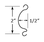
Optional curved slat for use on service doors to 16′ wide. Available in 22 or 20 gauge galvanized steel. Also for use in fire doors to 15′ wide.
Optional flat slat for use on service doors to 16′ wide. Available in 22 or 20 gauge galvanized steel or 22 gage stainless steel. Also for use on fire doors to 15′ wide, counter fire doors and counter doors.
Steel slats are galvanized per ASTM standards, treated for paint adhesion and pre-finished before forming with a prime coat and baked-on grey or tan polyester top coat.
Testing Agency
Underwriters Laboratories
Warnock Hersey
File Number
R-9560
R-9560
Hourly Rating
3 Hour
1 1/2 Hour
Wall Construction
Masonry
Drywall or Masonry
Jamb Type
Concrete
Block
Brick
16 ga. (min) Steel Stud,
Steel Tube, Wood Stud, Concrete, Block, Brick
Label Size
12′ Wide
12′ High
120 Sq. Ft. Max.
12′ Wide
12′ High
120 Sq. Ft. Max.
.
Oversized
24′ Wide
24′ High
579 Sq. Ft. Max.
24′ Wide
24′ High
579 Sq. Ft. Max.
Jambs must be continuous members from floor to structure above. Sizes and attachment of members is to be determined to provide adequate mounting and support for the size and weight of the door.By Method of Operation- Face of Wall Mount
RFP – Push-UP
RFC – Chain
RFA – Awning Crank
RFM – MotorFor Between-Jamb Mount, change letter ‘F’ to ‘J’
